Defining the Xinput USB Device
![]()
Teensyduino is set up to define USB devices through the usb_desc.h file. So we arae going to want to add the following code to this file:
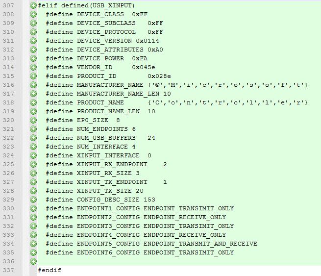
#elif defined(USB_XINPUT)
  #define DEVICE_CLASS  0xFF
  #define DEVICE_SUBCLASS  0xFF
  #define DEVICE_PROTOCOL  0xFF
  #define DEVICE_VERSION 0x0114
  #define DEVICE_ATTRIBUTES 0xA0
  #define DEVICE_POWER  0xFA
  #define VENDOR_ID    0x045e
  #define PRODUCT_ID    0x028e
  #define MANUFACTURER_NAME  {'©','M','i','c','r','o','s','o','f','t'}
  #define MANUFACTURER_NAME_LEN  10
  #define PRODUCT_NAME    {'C','o','n','t','r','o','l','l','e','r'}
  #define PRODUCT_NAME_LEN  10
  #define EP0_SIZE  8
  #define NUM_ENDPOINTS  6
  #define NUM_USB_BUFFERS  24
  #define NUM_INTERFACE  4
  #define XINPUT_INTERFACE  0
  #define XINPUT_RX_ENDPOINT  2
  #define XINPUT_RX_SIZE 3
  #define XINPUT_TX_ENDPOINT  1
  #define XINPUT_TX_SIZE 20
  #define CONFIG_DESC_SIZE 153
  #define ENDPOINT1_CONFIG ENDPOINT_TRANSIMIT_ONLY
  #define ENDPOINT2_CONFIG ENDPOINT_RECEIVE_ONLY
  #define ENDPOINT3_CONFIG ENDPOINT_TRANSIMIT_ONLY
  #define ENDPOINT4_CONFIG ENDPOINT_RECEIVE_ONLY
  #define ENDPOINT5_CONFIG ENDPOINT_TRANSMIT_AND_RECEIVE
  #define ENDPOINT6_CONFIG ENDPOINT_TRANSIMIT_ONLY
I placed these defines after USB_FLIGHTSIM and before the closing #endif. It does not matter where you place it as long as it is somewhere between the USB_SERIAL if defined and the closing end if statement. The first thing you may notice is that there is quite a bit of extra defines used here compared to some of the other devices. We need to add a lot of conditional statements into the USB code so that if these things are defined they are included however if they are not they need to default to what was previously in the library. These exist because our device is not HID nor is it generic. Normally for a HID device the class, subclass, and protocol are all the same, however we need to set them to whats known as Vendor Specific. You will see many more examples of this as we continue. The device class, subclass, and protocol are all set to 0xFF. This signifies to the host that these are vendor specific and handled by a driver. The device version is just a version number specified by the manufacturer. The device attributes are defined as 0xAD. The LSB is irrelevant to us because it is set as reserved in the USB spec. The MSB shows us that the device is bus powered and supports remote wake up. The device power is set to 0xFA, this is in 2mA units. That indicates that the device tells the host it can draw up to 500mA from the bus (0xFA is 250 * 2mA units = 500mA). This seems extremely high and can probably be calculated/measured and lowered, however, I just set it to the same as the 360 controller for simplicity’s sake. This may change in the future since it has caused issues with people not being able to use the device on their keyboards built-in USB hub. The VID and PID need to match something the driver is going to be looking for. The standard 360 controller has a vendor ID of 0x045e (Microsoft) and the product ID is 0x028e. I set the manufacturer name and product name the same as the controller. I don’t think this is necessary, but once again for maximum capability I added it in. Endpoint 0 is a reserved endpoint that is used to perform control transfers. This is what the host uses to probe the device and initialize it. Endpoint 0 has its size set to 8 bytes. We specify that the device has 6 endpoints, 24 buffers for USB, and 4 interfaces. In this project, we only have a real need to utilize interface 0. This interface does all of the button reporting and LED commands. For use later in the code we define interface 0 as XINPUT_INTERFACE. Endpoint 2 will be used as XINPUT_RX_ENDPOINT and will receive LED commands from the host in a packet that is 3 bytes long. Button reports will go out to the host on endpoint 1, which is defined as XINPUT_TX_ENDPOINT and the packets are 20 bytes long. We then define the configuration descriptor size to be 153. Since this project does not require the configuration descriptor to be dynamic, it is easiest to just define that size right here. The last thing we need to do is define the configuration of each endpoint for use later in the code.
The next step in creating this USB device is to write code for telling the host what type of device this is. The standard chain of events that we will see is the host will ask for the device descriptor and read it back until it grabs the length. Once it gets the length it will ask for the device descriptor again, but this time it will ask for the full descriptor specifying the length. It will then determine what configuration is needed (there is only one on this device) and ask for that configuration descriptor. We need to set up these two descriptors and the array of responses to queries from the host. This is done in the USB USB_DESC.c file. Since this file is set up for HID devices, the device descriptor is actually extremely generic. First we will go to where device_descriptor[] is defined and add the following lines:
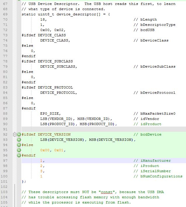
// USB Device Descriptor.  The USB host reads this first, to learn
// what type of device is connected.
static uint8_t device_descriptor[] = {
        18,                                     // bLength
        1,                                      // bDescriptorType
        0x00, 0x02,                             // bcdUSB
#ifdef DEVICE_CLASS
        DEVICE_CLASS,                           // bDeviceClass
#else
  0,
#endif
#ifdef DEVICE_SUBCLASS
        DEVICE_SUBCLASS,                        // bDeviceSubClass
#else
  0,
#endif
#ifdef DEVICE_PROTOCOL
        DEVICE_PROTOCOL,                        // bDeviceProtocol
#else
  0,
#endif
        EP0_SIZE,                               // bMaxPacketSize0
        LSB(VENDOR_ID), MSB(VENDOR_ID),         // idVendor
        LSB(PRODUCT_ID), MSB(PRODUCT_ID),       // idProduct
#ifdef DEVICE_VERSION              // bcdDevice
    LSB(DEVICE_VERSION), MSB(DEVICE_VERSION),
#else
        0x00, 0x01,
#endif
        1,                                      // iManufacturer
        2,                                      // iProduct
        3,                                      // iSerialNumber
        1                                       // bNumConfigurations
};
Normally the device has no need to specify a device version, however, the X360 does have a specific device version and this is the best way to include it without breaking support for other devices. The next part that we need to change is the configuration descriptor. The first thing we need to add to the configuration descriptor is the ability to define device attributes and device power, like so:
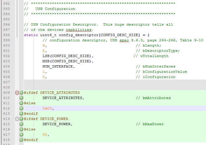
#ifdef DEVICE_ATTRIBUTES
    DEVICE_ATTRIBUTES,            // bmAttributes
#else
        0xC0,
#endif
#ifdef DEVICE_POWER
    DEVICE_POWER,              // bMaxPower
#else
        50,
#endif
Once we add in device attributes and power, we need to tell the compiler to include our controller descriptor when XINPUT_INTERFACE is defined. This configuration descriptor is gathered directly from the controller. It must match for the driver to work correctly. This tells the host about all the interfaces and endpoints that make up the device. I put comments on each line of the descriptor so that you can follow along and understand what each line means. Now we are going to add the following lines to config_descriptor[].
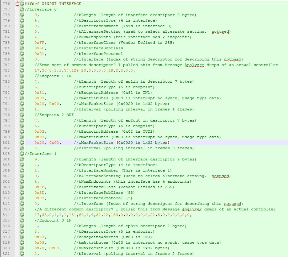
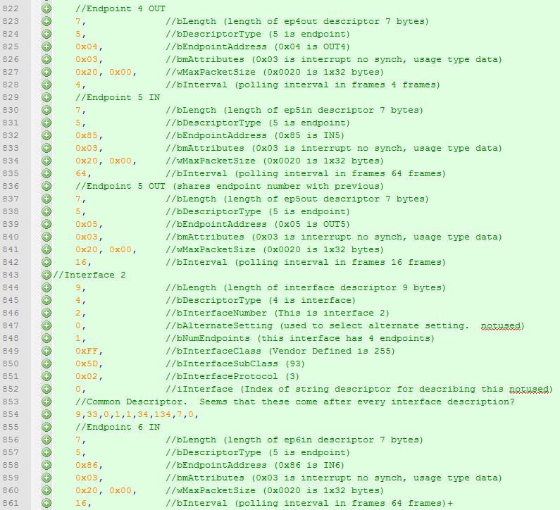
#ifdef XINPUT_INTERFACE
//Interface 0
9, //bLength (length of interface descriptor 9 bytes)
4, //bDescriptorType (4 is interface)
0, //bInterfaceNumber (This is interface 0)
0, //bAlternateSetting (used to select alternate setting. notused)
2, //bNumEndpoints (this interface has 2 endpoints)
0xFF, //bInterfaceClass (Vendor Defined is 255)
0x5D, //bInterfaceSubClass
0x01, //bInterfaceProtocol
0, //iInterface (Index of string descriptor for describing this notused)
//Some sort of common descriptor? I pulled this from Message Analyzer dumps of an actual controller
17,33,0,1,1,37,129,20,0,0,0,0,19,2,8,0,0,
//Endpoint 1 IN
7, //bLength (length of ep1in in descriptor 7 bytes)
5, //bDescriptorType (5 is endpoint)
0x81, //bEndpointAddress (0x81 is IN1)
0x03, //bmAttributes (0x03 is interrupt no synch, usage type data)
0x20, 0x00, //wMaxPacketSize (0x0020 is 1x32 bytes)
4, //bInterval (polling interval in frames 4 frames)
//Endpoint 2 OUT
7, //bLength (length of ep2out in descriptor 7 bytes)
5, //bDescriptorType (5 is endpoint)
0x02, //bEndpointAddress (0x02 is OUT2)
0x03, //bmAttributes (0x03 is interrupt no synch, usage type data)
0x20, 0x00, //wMaxPacketSize (0x0020 is 1x32 bytes)
8, //bInterval (polling interval in frames 8 frames)
//Interface 1
9, //bLength (length of interface descriptor 9 bytes)
4, //bDescriptorType (4 is interface)
1, //bInterfaceNumber (This is interface 1)
0, //bAlternateSetting (used to select alternate setting. notused)
4, //bNumEndpoints (this interface has 4 endpoints)
0xFF, //bInterfaceClass (Vendor Defined is 255)
0x5D, //bInterfaceSubClass (93)
0x03, //bInterfaceProtocol (3)
0, //iInterface (Index of string descriptor for describing this notused)
//A different common descriptor? I pulled this from Message Analyzer dumps of an actual controller
27,33,0,1,1,1,131,64,1,4,32,22,133,0,0,0,0,0,0,22,5,0,0,0,0,0,0,
//Endpoint 3 IN
7, //bLength (length of ep3in descriptor 7 bytes)
5, //bDescriptorType (5 is endpoint)
0x83, //bEndpointAddress (0x83 is IN3)
0x03, //bmAttributes (0x03 is interrupt no synch, usage type data)
0x20, 0x00, //wMaxPacketSize (0x0020 is 1x32 bytes)
2, //bInterval (polling interval in frames 2 frames)
//Endpoint 4 OUT
7, //bLength (length of ep4out descriptor 7 bytes)
5, //bDescriptorType (5 is endpoint)
0x04, //bEndpointAddress (0x04 is OUT4)
0x03, //bmAttributes (0x03 is interrupt no synch, usage type data)
0x20, 0x00, //wMaxPacketSize (0x0020 is 1x32 bytes)
4, //bInterval (polling interval in frames 4 frames)
//Endpoint 5 IN
7, //bLength (length of ep5in descriptor 7 bytes)
5, //bDescriptorType (5 is endpoint)
0x85, //bEndpointAddress (0x85 is IN5)
0x03, //bmAttributes (0x03 is interrupt no synch, usage type data)
0x20, 0x00, //wMaxPacketSize (0x0020 is 1x32 bytes)
64, //bInterval (polling interval in frames 64 frames)
//Endpoint 5 OUT (shares endpoint number with previous)
7, //bLength (length of ep5out descriptor 7 bytes)
5, //bDescriptorType (5 is endpoint)
0x05, //bEndpointAddress (0x05 is OUT5)
0x03, //bmAttributes (0x03 is interrupt no synch, usage type data)
0x20, 0x00, //wMaxPacketSize (0x0020 is 1x32 bytes)
16, //bInterval (polling interval in frames 16 frames)
//Interface 2
9, //bLength (length of interface descriptor 9 bytes)
4, //bDescriptorType (4 is interface)
2, //bInterfaceNumber (This is interface 2)
0, //bAlternateSetting (used to select alternate setting. notused)
1, //bNumEndpoints (this interface has 4 endpoints)
0xFF, //bInterfaceClass (Vendor Defined is 255)
0x5D, //bInterfaceSubClass (93)
0x02, //bInterfaceProtocol (3)
0, //iInterface (Index of string descriptor for describing this notused)
//Common Descriptor. Seems that these come after every interface description?
9,33,0,1,1,34,134,7,0,
//Endpoint 6 IN
7, //bLength (length of ep6in descriptor 7 bytes)
5, //bDescriptorType (5 is endpoint)
0x86, //bEndpointAddress (0x86 is IN6)
0x03, //bmAttributes (0x03 is interrupt no synch, usage type data)
0x20, 0x00, //wMaxPacketSize (0x0020 is 1x32 bytes)
16, //bInterval (polling interval in frames 64 frames)+
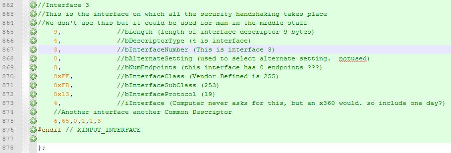
//Interface 3
//This is the interface on which all the security handshaking takes place
//We don't use this but it could be used for man-in-the-middle stuff
9, //bLength (length of interface descriptor 9 bytes)
4, //bDescriptorType (4 is interface)
3, //bInterfaceNumber (This is interface 3)
0, //bAlternateSetting (used to select alternate setting. notused)
0, //bNumEndpoints (this interface has 0 endpoints ???)
0xFF, //bInterfaceClass (Vendor Defined is 255)
0xFD, //bInterfaceSubClass (253)
0x13, //bInterfaceProtocol (19)
4, //iInterface (Computer never asks for this, but an x360 would. so include one day?)
//Another interface another Common Descriptor
6,65,0,1,1,3
#endif // XINPUT_INTERFACE
You will notice that the iInterface value for interface 3 states a value of 4. This means that string 4 contains a descriptor for this interface. This is the security interface used to handshake with an actual XBOX 360. We really do not need this, however, anyone that might try a man in the middle style device will need this. The 360 will cease communication with the device if this string is not returned. So we define a structure of type usb_string_descriptor_struct and fill it with the correct string.
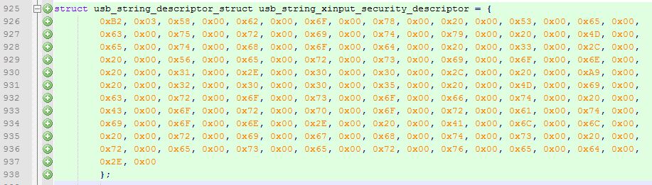
struct usb_string_descriptor_struct usb_string_xinput_security_descriptor = {
    0xB2, 0x03, 0x58, 0x00, 0x62, 0x00, 0x6F, 0x00, 0x78, 0x00, 0x20, 0x00, 0x53, 0x00, 0x65, 0x00,
    0x63, 0x00, 0x75, 0x00, 0x72, 0x00, 0x69, 0x00, 0x74, 0x00, 0x79, 0x00, 0x20, 0x00, 0x4D, 0x00,
    0x65, 0x00, 0x74, 0x00, 0x68, 0x00, 0x6F, 0x00, 0x64, 0x00, 0x20, 0x00, 0x33, 0x00, 0x2C, 0x00,
    0x20, 0x00, 0x56, 0x00, 0x65, 0x00, 0x72, 0x00, 0x73, 0x00, 0x69, 0x00, 0x6F, 0x00, 0x6E, 0x00,
    0x20, 0x00, 0x31, 0x00, 0x2E, 0x00, 0x30, 0x00, 0x30, 0x00, 0x2C, 0x00, 0x20, 0x00, 0xA9, 0x00,
    0x20, 0x00, 0x32, 0x00, 0x30, 0x00, 0x30, 0x00, 0x35, 0x00, 0x20, 0x00, 0x4D, 0x00, 0x69, 0x00,
    0x63, 0x00, 0x72, 0x00, 0x6F, 0x00, 0x73, 0x00, 0x6F, 0x00, 0x66, 0x00, 0x74, 0x00, 0x20, 0x00,
    0x43, 0x00, 0x6F, 0x00, 0x72, 0x00, 0x70, 0x00, 0x6F, 0x00, 0x72, 0x00, 0x61, 0x00, 0x74, 0x00,
    0x69, 0x00, 0x6F, 0x00, 0x6E, 0x00, 0x2E, 0x00, 0x20, 0x00, 0x41, 0x00, 0x6C, 0x00, 0x6C, 0x00,
    0x20, 0x00, 0x72, 0x00, 0x69, 0x00, 0x67, 0x00, 0x68, 0x00, 0x74, 0x00, 0x73, 0x00, 0x20, 0x00,
    0x72, 0x00, 0x65, 0x00, 0x73, 0x00, 0x65, 0x00, 0x72, 0x00, 0x76, 0x00, 0x65, 0x00, 0x64, 0x00,
    0x2E, 0x00
    };
Finally we need to add the command used to ask for this string and specify a response in the usb_descriptor_list[] array. The host will send a request for 0x0304. The 0x03 portion indicates the host wants a string. The 0x04 is the index, which as you remember, is the index we specified as interface 3’s iInterface. We then tell the device to return security descriptor string we just set up.
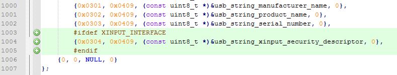
#ifdef XINPUT_INTERFACE
{0x0304, 0x0409, (const uint8_t *)&usb_string_xinput_security_descriptor, 0},
#endif