The XBOX 360 Controller
With the need for drivers, there was no way to roll my own solution. Asking everyone to put their 64-bit version of windows into test mode just to use this controller seemed a little insane. My only real option at this point was to imitate something that existed. It most likely would have been easier to reproduce a more simple PC only controller (ie the F310). The PC only controllers have a lot less interfaces and endpoints, but I already had 360 controllers and did not feel like buying anything new.
My favorite resource for how the controller operates is the Free60 gamepad wiki page. The 360 controller is a HID controller with the HID report descriptor removed and the device class, subclass, and protocol set to 0xFF (255). This ensures that the HID driver does not attach to the device so the Microsoft driver can pick it up. The vendor ID is 0x45e (Microsoft) and the product ID is 0x028e. Once you set the device to the same VID and PID the driver will attach to the driver and attempt to enumerate it.
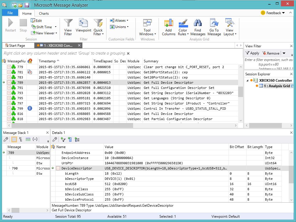
There are only two descriptors you need to worry about for the controller. This is because there is no HID report descriptor. There is the device descriptor, which tells the host things such as USB version, device class, device subclass, device protocol, max packet size for endpoint 0, VID, PID, etc. The other descriptor is the configuration descriptor, which tells the host about the device configuration, each interface, and their endpoints. The configuration descriptor listed on Free60 is not the entire descriptor. I had to pull one from the controller using Microsoft Message Analyzer. There is some padding included in the controller’s actual configuration and that padding needs to be there for the device to correctly enumerate. I will try to do my best at explaining the configuration descriptor. This will not be an in depth explanation of the entire descriptor. You should read the comments included in my code, USB in a Nutshell, and consider picking up a copy of USB Complete. A fair warning though, USB complete focuses mainly on the PC side of coding for USB devices. When I first studied USB for embedded devices I needed to create PC side software to configure the device over generic HID. Jan Axelson’s book was a tremendous resource in developing my PC USB library and understanding the underlying elements of USB.
// USB Configuration Descriptor.  This huge descriptor tells all
// of the devices capbilities.
static uint8_t config_descriptor[CONFIG_DESC_SIZE] = {
    // configuration descriptor, USB spec 9.6.3, page 264-266, Table 9-10
    9,                                                          // bLength;
    2,                                                          // bDescriptorType;
    LSB(CONFIG_DESC_SIZE),            // wTotalLength
    MSB(CONFIG_DESC_SIZE),
    NUM_INTERFACE,                          // bNumInterfaces
    1,                                                         // bConfigurationValue
    0,                                                         // iConfiguration
    #ifdef DEVICE_ATTRIBUTES
      DEVICE_ATTRIBUTES,                // bmAttributes
    #else
      0xC0,
    #endif
    #ifdef DEVICE_POWER
      DEVICE_POWER,                         // bMaxPower
    #else
      50,
    #endif
The configuration descriptor first tells the PC it is a configuration type descriptor (0x02) with a length of 9. It then tells us that this is describing configuration 1 and that there are 4 interfaces in this configuration. The device is bus powered and has a max power draw of 500mA. It describes the total length of the configuration descriptor as 153 which we can get from the original controller descriptor or by counting bytes. However, as I discussed earlier, you will notice that the descriptor listed at Free60 comes out to 93 or 94 bytes. This is because the padding is missing and trust me you need the padding. Interface 0 has an interface class of 0xFF, subclass 0x5D, and a protocol of 0x01. This interface is actually the only one that concerns us on the PC. It contains two endpoints, 0x81 (Endpoint 1 in) and 0x02 (Endpoint 2 out). The directions are based from the host’s point of view and are described in the MSB of the endpoint address. With setting the most significant bit to a 1 making the endpoint an IN. This means that all button reports going TO the PC with be sent on endpoint 0x81, while any LED patterns the PC sends the controller are being RECEIVED by the device on endpoint 0x02. The other endpoints are used for other peripheral such as headsets, chatpads, etc. The only other interface that might be of use to you is the last one, interface 4. It claims it has 0 endpoints, but this is the interface that handles the security handshake with the Infineon security chip. It is the only interface with a string descriptor. I have included this string descriptor just in case someone decides they want to attempt to replicate a man in the middle device similar to what BrandonW created. In emails between myself and Brandon, he indicated that the 360 will just stop communicating with the controller if this string descriptor for interface 4 doesn’t exist.
The next thing that we need to look at, is the way the controller sends button reports to the host. Once again, Free60 is on top of things with this. However, pay close attention to the indexes provided. The standard bit format of a byte goes: bit 7, bit 6, bit 5, bit 4, bit 3, bit 2, bit 1, and bit 0. Remember this is sent from the device to the host on endpoint 1 in a 20 byte packet. Below is the button report broken down:
As you write your code, you may wonder what the button names correlate to on an XBOX 360 controller. Here is a table to help you with that:
The last endpoint we really care about is endpoint 2 out. This comes into the device from the PC and contains messages. The only message we care about is message type 0x01, which is LED control. The packet will come in 3 bytes with byte 1 being message type and byte 2 as the length. The 3rd byte contains the pattern to be performed. Below are the different patterns that the controller can produce: